|
|
|
|
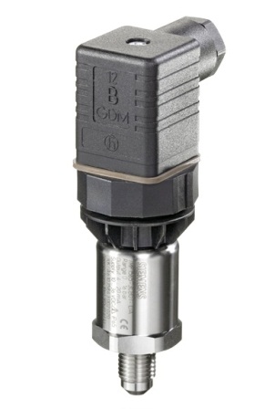

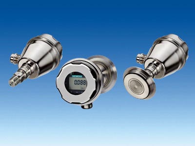
SITRANS P200/P210/P220
|
|
Mã sản phẩm:
7MF1565/7MF1566/7MF1567
Tên sản phẩm:
SITRANS P200/P210/P220
Description
The SITRANS transmitters P200, P210 and P220 are compact single-range-transmitters for measurement of absolute and gauge pressure.
In this series we use two different kinds of pressure sensors: two stainless steel sensors and one ceramics sensor. So the measurement of process pressure, absolute pressure and hydrostatic pressure is an easy thing. The measured pressure will be transformed with these sensors into a 4…20-mA- resp. a 0…10-V-signal.
Benefits- High measuring accuracy
- Rugged stainless steel enclosure
- High overload withstand capability
- For aggressive and non-aggressive media
- For measuring the pressure of liquids, gases and vapors
- Compact design
Detail| Nonlinearity | ≤ 0,25 % | | Long-term stability | ≤ 0,25% / 12 Monate | | Measuring range | SITRANS P200: 1 bar to 60 bar gauge 0,6 bar to 16 bar absolute | | | SITRANS P210: 100 mbar to 600 mbar gauge | | | SITRANS P220: 2,5 bar to 600 bar gauge |
|
|
|
|
|
|
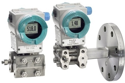

SITRANS P500
|
|
Mã sản phẩm:
7MF56.3
Tên sản phẩm:
SITRANS P500
Description
The SITRANS P500 has been developed to meet the highest expectations for measuring accuracy, ruggedness, and user-friendliness, and it merges seamlessly into the SITRANS P family. With the SITRANS P500, you can expect pressure measurement at the highest level.
It guarantees an accuracy of ≤ 0.03 % as well as outstanding values for the influence of static pressure and temperature on the measured result. In this way, it guarantees a total performance of ≤ 0.14 % up to a turndown of 10:1. Since this feature means that only one measuring cell can be used for different measuring ranges, inventory costs can be significantly reduced without the need for losses in the quality of the measured result. The high long-term stability of the sensor also reduces maintenance costs thanks to extended calibration intervals, and ensures that you can always rely on the measured results in the long term.
An innovated sensor assembly enables direct-connected use in process temperatures
of up to 125 °C (257 °F) even without a remote seal system. With an improved 3-pushbutton operator input concept for setting the device, the SITRANS P500‘s host of diagnostics options can be used conveniently without software.
Even curve displays and trend diagrams can be represented on the display for user-friendly process monitoring.
Benefits- Highest measuring accuracy
- Extremely short step response
- Outstanding values for the long-term stability
- Optimized operator input: Can be set with a high degree of user-friendliness via a full-text-enabled, backlit display and 3 pushbuttons. The transmitter can also be configured and operated conveniently from the control system using the HART protocol
- Easy configuration via HART with improved EDD* including a new quick start wizard
- Extensive diagnostics such as 8 min/max pointers for process values showing also the time of the event
- Process temperature up to 125 °C (257 °F) possible without remote seals
- Backlit, graphics-enabled display
- Space-savings thanks to process flanges of only 86 mm (3.4“) in length
*EDD: Electronic device description
Detail| Accuracy | ≤ 0,03 % (for a TurnDown up to 10) | | Long-term stability | 0.05 % / 5 years | | Measuring range | 0 - 1,25 mbar bis 0 - 1250 mbar |
|
|
|
|
|
|
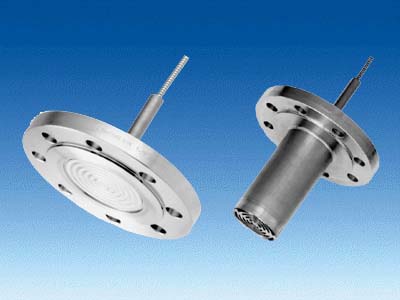

Remote seals of flange design
|
|
Mã sản phẩm:
7MF4920/7MF4921/7MF4923
Tên sản phẩm:
Remote seals of flange design
Diaphragm seals of flange design are available for the following SITRANS P pressure transmitter series:- For pressure: MK II, P300, DS III, DS III PA
- For absolute pressure: P300, DS III, DS III PA
- For differential pressure and flow: DS III, DS III PA
|
|
|
|
|
|
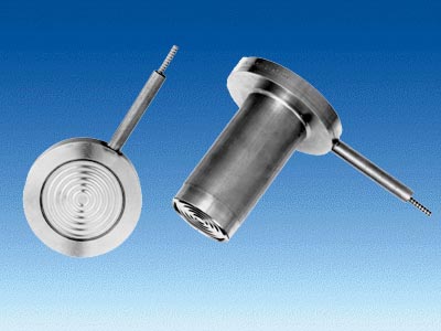

Remote seals of sandwich design
|
|
Mã sản phẩm:
7MF4900/7MF4901/7MF4903
Tên sản phẩm:
Remote seals of sandwich design
Diaphragm seals of sandwich design exist optionally with a projecting diaphragm (tube) and are available for the following SITRANS P pressure transmitter series:- For pressure: MK II, P300, DS III, DS III PA
- For absolute pressure: P300, DS III, DS III PA
- For differential pressure and flow: DS III, DS III PA
|
|
|
|
|
|
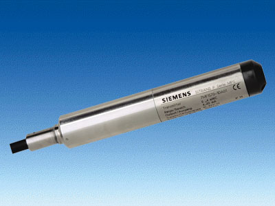

MPS series
|
|
Mã sản phẩm:
7MF1570
Tên sản phẩm:
MPS series
SITRANS P pressure transmitters, MPS series (submersible sensor) |
|---|
Mode of operation | | Measuring principle | Piezo-resistive | Input | | Measured variable | Hydrostatic level | Measuring range | Maximum operating pressure | - 0 ... 2 mH2O (0 ... 6 ftH2O)
| - 1.4 bar (20.3 psi) (corresponds to 14 mH2O (42 ftH2O))
| - 0 ... 4 mH2O (0 ... 12 ftH2O)
| - 1.4 bar (20.3 psi) (corresponds to 14 mH2O (42 ftH2O))
| - 0 ... 5 mH2O (0 ... 15 ftH2O)
| - 1.4 bar (20.3 psi) (corresponds to 14 mH2O (42 ftH2O))
| - 0 ... 6 mH2O (0 ... 18 ftH2O)
| - 3.0 bar (43.5 psi) (corresponds to 30 mH2O (90 ftH2O))
| - 0 ... 10 mH2O (0 ... 30 ftH2O)
| - 3.0 bar (43.5 psi) (corresponds to 30 mH2O (90 ftH2O))
| - 0 ... 20 mH2O (0 ... 60 ftH2O)
| - 6.0 bar (87.0 psi) (corresponds to 60 mH2O (180 ftH2O))
| Output | | Output signal | 4 ... 20 mA | Accuracy | to EN 60770-1 | Error in measurement (including non-linearity, hysteresis and repeatability, at 25 °C (77 °F)) | 0.3 % of full-scale value (typical) | Influence of ambient temperature | | Zero and span | | - 1 ... 6 mH2O (3 ... 18 ftH2O)
| 0.45 %/10 K of full-scale value | | 0.3 %/10 K of full-scale value | Long-term stability | | Zero and span | | - 1 ... 6 mH2O (3 ... 18 ftH2O)
| 0.25 % of full-scale value/year | | 0.2 % of full-scale value/year | Rated operating conditions | | Ambient conditions | | | -10 ... +80 °C (+14 ... +176 °F) | | -40 ... +100 °C (-40 ... +212 °F) | Degree of protection to DIN EN 60529 | IP68 | Design | | Approx. weight | | | ≈ 0.4 kg (≈ 0.88 lb) | | 0.08 kg/m (≈ 0.054 lb/ft) | Electrical connection | Cable with 2 conductors with screen and vent pipe, strength cord (max. 300 N (67.44 lbf)) | Material | | | Stainless steel, mat. No. 1.4571/316 Ti | | Stainless steel, mat. No. 1.4571/316 Ti | | Viton | | Optionally
PE/HFFR sheath (non-halogen)
or
FEP sheath | Power supply | | Terminal voltage on pressure transmitter (UB) | 10 ... 36 V DC | Certificate and approvals | | The transmitter is not subject to the pressure equipment directive (DGRL 97/23/EC) | Explosion protection | | | TÜV 03 ATEX 2004X | | Ex II 1 G EEx ia IIC T4 |
Junction box | |
|---|
Application | for connecting the transmitter cable | Design | | Weight | 0.2 kg (0.44 lb) | Electrical connection | 2x 3-way (28 ... 18 AWG) | Cable entry | 2x M20x1.5 | Enclosure material | polycarbonate | Vent pipe for atmospheric pressure | | Screw for cable strength cord | | Rated operating conditions | | Degree of protection to DIN EN 60529 | IP54 |
Cable hanger | |
|---|
Application | for mounting the transmitter | Design | | Weight | 0.16 kg (0.35 lb) | Material | Galvanized steel, polyamide |
|
|
|
|
|
|
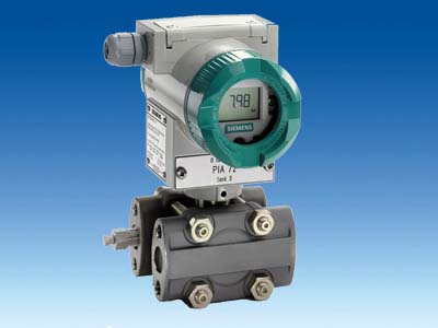

SITRANS P DS III For absolute pressure (from the differential pressure series)
|
|
Mã sản phẩm:
7MF4333/7MF4334/7MF4335
Tên sản phẩm:
SITRANS P DS III For absolute pressure (from the differential pressure series)
SITRANS P, DS III series for absolute pressure (from the differential pressure series) |
|---|
| | HART | PROFIBUS PA or Foundation fieldbus | Input | | Measured variable | Absolute pressure | Spans (infinitely adjustable) or
nominal measuring range and
max. permissible operating pressure | Span | Maximum operating pressure | Nominal measuring range | Maximum operating pressure | | | 8.3 ... 250 mbar a
(0.12 ... 3.6 psi a) | 32 bar a
(464 psi a) | 250 mbar a
(3.6 psi a) | 32 bar a
(464 psi a) | | | 43 ... 1300 mbar a
(0.62 ... 18.9 psi a) | 32 bar a
(464 psi a) | 1300 bar a
(18.9 psi a) | 32 bar a
(464 psi a) | | | 160 ... 5000 mbar a
(2.32 ... 72.5 psi a) | 32 bar a
(464 psi a) | 5 bar a
(72.5 psi a) | 32 bar a
(464 psi a) | | | 1 ... 30 bar a
(14.5 ... 435 psi a) | 160 bar a
(2320 psi a) | 30 bar a
(435 psi a) | 160 bar a
(2320 psi a) | | | 5.3 ... 100 bar a
(76.9 ... 1450 psi a) | 160 bar a
(2320 psi a)
(for connection thread M10 and7/16-20 UNF in the process flanges) | 100 bar a
(1450 psi a) | 160 bar a
(2320 psi a)
(for connection thread M10 and7/16-20 UNF in the process flanges) | Lower measuring limit | | | - Measuring cell with silicone oil filling
| 0 mbar a (0 psi a) | Upper measuring limit | 100% of max. span | Output | | | Output signal | 4 ... 20 mA | Digital PROFIBUS PA or Foundation fieldbus signal | - Lower limit (infinitely adjustable)
| 3.55 mA, factory preset to 3.84 mA | - | - Upper limit (infinitely adjustable)
| 23 mA, factory preset to 20.5 mA or optionally set to 22.0 mA | - | Load | | - Without HART communication
| R B ≤ (UH - 10.5 V)/0.023 A in Ω,
UH : Power supply in V | - | | R B = 230 ... 500 Ω (SIMATIC PDM) or
RB = 230 ... 1100 Ω (HART Communicator) | - | Physical bus | - | IEC 61158-2 | With polarity reversal protection | - | Yes | Measuring accuracy | Acc. to EN 60770-1 | Reference conditions
(All error data refer always refer to the set span) | Increasing characteristic, start-of-scale value 0 bar, stainless steel seal diaphragm, silicone oil filling, room temperature 25 °C (77 °F)) r: Span ratio
(r = max. span / set span) | Error in measurement and fixed-point setting (including hysteresis and repeatability) | | | | ≤ 0.1 % | | ≤ 0.1 % | | | ≤ 0.2 % | | Long-term drift (temperature change ±30 °C (±54 °F)) | ≤ (0.1 · r)%/year | ≤ 0.1 %/year | Influence of ambient temperature | | - at -10 ... +60 °C (14 ... 140 °F)
| ≤ (0.1 · r + 0.2)% | ≤ 0.3 % | - at -40 ... -10 °C and +60 ... +85 °C
(-40 ... +14 °F and 140 ... 185 °F)
| ≤ (0.1·r + 0.15) %/10 K | ≤ 0.25 %/10 K | Measured Value Resolution | - | 3 · 10-5 of nominal measuring range | Conditions of use | | Degree of protection (to EN 60529) | IP65 | Temperature of medium | | - Measuring cell with silicone oil filling
| -40 ... +100 °C (-40 ... +212 °F) | - Measuring cell with inert filling liquid
| -20 ... +100 °C (-4 ... +212 °F) | - In conjunction with dust explosion protection
| -20 ... +60 °C (-4 ... +140 °F) | Ambient conditions | | | | | -30 ... +85 °C (-22 ... +185 °F) | | -50 ... +85 °C (-58 ... +185 °F) | | | | Permissible | - Electromagnetic Compatibility
| | | Acc. to EN 50081-1 | | Acc. to EN 61326 and NAMUR NE 21 | Design | | Weight (without options) | ≈ 4.5 kg (≈ 9.9 lb) | Enclosure material | Low-copper die-cast aluminum, GD-AlSi 12 or stainless steel precision casting, Mat. No. 1.4408 | Wetted parts materials | | | Stainless steel, mat. No. 1.4404/316L or Hastelloy C276, mat. No. 2.4819, Monel, mat. No. 2.4360, tantalum or gold | - Process flanges and sealing screw
| Stainless steel, mat. No. 1.4408, Hastelloy C4, mat. No. 2.4610 or Monel, mat. No. 2.4360 | | FPM (Viton) or optionally: PTFE, FEP, FEPM and NBR | Measuring cell filling | Silicone oil or inert filling liquid (max. 160 bar (2320 psi a) with oxygen measurement) | Process connection | ¼-18 NPT and flange connection with mounting thread M10 to DIN 19213 or 7/16-20 UNF to EN 61518 | Material of mounting bracket | | | Sheet-steel, Mat. No. 1.0330, chrome-plated | | Sheet stainless steel, mat. No. 1.4301 (SS 304) | Power supply U H | | Supplied through bus | Terminal voltage on transmitter | 10.5 ... 45 V DC
10.5 ... 30 V DC in intrinsically-safe mode | - | Separate 24 V power supply necessary | - | No | Bus voltage | | | - | 9 ...32 V | - With intrinsically-safe operation
| - | 9 ...24 V | Current consumption | | | - | 12.5 mA | - Startup current ≤ basic current
| - | Yes | - Max. current in event of fault
| - | 15.5 mA | Fault disconnection electronics (FDE) available | - | Yes | Certificates and approvals | | | Classification according to PED 97/23/EC | For gases of fluid group 1 and liquids of fluid group 1; complies with requirements of article 3, paragraph 3 (sound engineering practice) | Explosion protection | | | PTB 99 ATEX 2122 | | Ex II 1/2 G EEx ia/ib IIB/IIC T6 | - Permissible ambient temperature
| -40 ... +85 °C (-40 ... +185 °F) temperature class T4;
-40 ... +70 °C (-40 ... +158 °F) temperature class T5;
-40 ... +60 °C (-40 ... +140 °F) temperature class T6 | | To certified intrinsically-safe circuits with maximum values:
Ui = 30 V, Ii = 100 mA,
Pi = 750 mW; Ri = 300 Ω | FISCO supply unit:
Uo = 17.5 V, Io = 380 mA, Po = 5.32 W Linear barrier:
Uo = 24 V, Io = 250 mA,Po = 1.2 W | - Effective internal inductance/capacitance
| L i = 0.4 mH, Ci = 6 nF | L i = 7 μH, Ci = 1.1 nF | | PTB 99 ATEX 1160 | | Ex II 1/2 G EEx d IIC T4/T6 | - Permissible ambient temperature
| -40 ... +85 °C (-40 ... +185 °F) temperature class T4;
-40 ... +60 °C (-40 ... +140 °F) temperature class T6 | | To circuits with values:UH = 10.5 ... 45 V DC | To circuits with values:UH = 9 ... 32 V DC | - Dust explosion protection for zone 20
| PTB 01 ATEX 2055 | | Ex II 1 D IP65 T 120 °C
Ex II 1/2 D IP65 T 120 °C | - Permissible ambient temperature
| -40 ... +85 °C (-40 ... +185 °F) | | 120 °C (248 °F) | | To certified intrinsically-safe circuits with maximum values:
Ui = 30 V, Ii = 100 mA,
Pi = 750 mW, Ri = 300 Ω | FISCO supply unit:
Uo = 17.5 V, Io = 380 mA, Po = 5.32 W Linear barrier:
Uo = 24 V, Io = 250 mA,Po = 1.2 W | - Effective internal inductance/capacitance
| L i = 0.4 mH, Ci = 6 nF | L i = 7 μH, Ci = 1.1 nF | - Dust explosion protection for zone 21/22
| PTB 01 ATEX 2055 | | Ex II 2 D IP65 T 120 °C | | To circuits with values:UH = 10.5 ... 45 V DC;Pmax = 1.2 W | To circuits with values:UH = 9 ... 32 V DC; Pmax= 1.2 W | - Type of protection "n" (zone 2)
| TÜV 01 ATEX 1696 X | Planned | | Ex II 3 G EEx nA L IIC T4/T5/T6 | - | - Explosion protection acc. to FM
| Certificate of Compliance 3008490 | - Identification (XP/DIP) or (IS); (NI)
| CL I, DIV 1, GP ABCD T4...T6; CL II, DIV 1, GP EFG; CL III; CL I, ZN 0/1 AEx ia IIC T4...T6; CL I, DIV 2, GP ABCD T4...T6; CL II, DIV 2, GP FG; CL III | - Explosion protection to CSA
| Certificate of Compliance 1153651 | - Identification (XP/DIP) or (IS)
| CL I, DIV 1, GP ABCD T4...T6; CL II, DIV 1, GP EFG; CL III; Ex ia IIC T4...T6; CL I, DIV 2, GP ABCD T4...T6; CL II, DIV 2, GP FG; CL III |
HART communication | |
|---|
HART communication | 230 ... 1100 Ω | Protocol | HART Version 5.x | Software for computer | SIMATIC PDM |
PROFIBUS PA communication | |
|---|
Simultaneous communication with master class 2 (max.) | 4 | The address can be set using | Configuration tool or local operation (standard setting address 126) | Cyclic data usage | | | 5 (one measured value) or
10 (two measured values) | | 0, 1, or 2 (register operating mode and reset function for metering) | Internal preprocessing | | Device profile | PROFIBUS PA Profile for Process Control Devices Version 3.0, Class B | Function blocks | 2 | | | - Adaptation to customer-specific process variables
| Yes, linearly rising or falling characteristic | - Electrical damping T63 , adjustable
| 0 to 100 s | | Input /Output | | parameterizable (last good value, substitute value, incorrect value) | | Yes, one upper and lower warning limit and one alarm limit respectively | | Can be reset, preset, optional direction of counting, simulation function of register output | | parameterizable (summation with last good value, continuous summation, summation with incorrect value) | | One upper and lower warning limit and one alarm limit respectively | | 1 | Transducer blocks | 2 | - Pressure transducer block
| | - Can be calibrated by applying two pressures
| Yes | - Monitoring of sensor limits
| Yes | - Specification of a container characteristic with
| Max. 30 nodes | - Square-rooted characteristic for flow measurement
| Yes | - Gradual volume suppression and implementation point of square-root extraction
| Parameterizable | - Simulation function for measured pressure value and sensor temperature
| Constant value or over parameterizable ramp function |
Communication Foundation fieldbus | |
|---|
Function blocks | 3 function blocks analog input, 1 function block PID | | | - Adaptation to customer-specific process variables
| Yes, linearly rising or falling characteristic | - Electrical damping T63 , adjustable
| 0 to 100 s | | Output/input (can be locked within the device with a bridge) | | parameterizable (last good value, substitute value, incorrect value) | | Yes, one upper and lower warning limit and one alarm limit respectively | - Square-rooted characteristic for flow measurement
| Yes | | Standard FF function block | | 1 resource block | Transducer blocks | 1 transducer block Pressure with calibration, 1 transducer block LCD | - Pressure transducer block
| | - Can be calibrated by applying two pressures
| Yes | - Monitoring of sensor limits
| Yes | - Simulation function: Measured pressure value, sensor temperature and electronics temperature
| Constant value or over parameterizable ramp function |
|
|
|
|
|
|
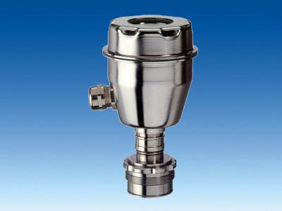

P300 with PMC connection
|
|
Mã sản phẩm:
7MF8123/7MF8124/7MF8125
Tên sản phẩm:
P300 with PMC connection
SITRANS P300 for relative pressure with PMC connection for the paper industry |
|---|
| | HART | PROFIBUS PA | input | | Measured variable | Gage pressure (flush-mounted) | Spans (infinitely adjustable) or
nominal measuring range and
max. pemissible test pressure | Measured span | Max. perm. test pressure | Nominal measuring range | Max. perm. test pressure | | | 0.01 ... 1 bar g
(0.15 ... 14.5 psi g) | 6 bar g
(87 psi g) | 1 bar g
(14.5 psi g) | 6 bar g
(87 psi g) | | | 0.04 ... 4 bar g
(0.58 ... 58 psi g) | 10 bar g
(145 psi g) | 4 bar g
(58 psi g) | 10 bar g
(145 psi g) | | | 0.16 ... 16 bar g
(2.3 ... 232 psi g) | 32 bar g
(464 psi g) | 16 bar g
(232 psi g) | 32 bar g
(464 psi g) | | | Depending on the process connection, the span may differ from these values | Depending on the process connection, the nominal measuring range may differ from these values | Lower measuring limit | | - Measuring cell with silicone oil
| 100 mbar a (1.45 psi a) | Upper measuring limit | | - Measuring cell with silicone oil
| 100 % of max. span | 100 % of the max. nominal measuring range | Output | | Output signal | 4 ... 20 mA | Digital PROFIBUS PA signal | Physical bus | - | IEC 61158-2 | With polarity reversal protection | No | Yes | Electrical damping T63(step width 0.1 s) | Set to 0.1 s (0 ... 100 s) | Measuring accuracy | to EN 60770-1 | Reference conditions | Increasing characteristic, start-of-scale value 0 bar, stainless steel seal diaphragm, measuring cell with silicone oil, room temperature 25 °C (77 °F), span ratio (r = max. span / set span) | Measurement deviation with cut-off point setting, including hysteresis and repeatability. | | Linear characteristic curve | | ≤ 0.075 % | | ≤ (0.0029 · r + 0.071)% | | | ≤ (0.0045 · r + 0.071)% | | | ≤ (0.005 · r + 0.05)% | | Settling time T63 without electrical damping | Approx. 0.2 s | Long-term drift at ±30 °C (±54 °F) | ≤ (0.25 · r)%/5 years | ≤ 0.25 %/5 years | Influence of ambient temperature | | - at -10 ... +60 °C (14 ... 140 °F)
| ≤ (0.1 · r + 0.2)% | ≤ 0.3 % | - at -40 ... -10 °C and +60 ... +85 °C
(-40 ... 14 °F and 140 ... 185 °F)
| ≤ (0.1·r + 0.15) %/10 K | ≤ 0.25 %/10 K | Influence of the medium temperature (only with front-flush diaphragm) | | - Temperature difference between medium temperature and ambient temperature
| 3mbar/10 K (0.04 psi/10 K) | Rated conditions | | Installation conditions | | Ambient temperature | Observe the temperature class in areas subject to explosion hazard. | - Measuring cell with silicone oil
| -40 ... +85 °C (-40 ... +185 °F) | | -30 ... +85 °C (-22 ... +185 °F) | | -50 ... +85 °C (-58 ... +185 °F) | Climatic category | | Condensation | Permissible | Degree of protection to EN 60529 | IP65, IP68, NEMA X, enclosure cleaning, resistant to lyes, steam to 150° C (302 °F) | Electromagnetic compatibility | | - Emitted interference and noise immunity
| To EN 61326 and NAMUR NE 21 | Medium conditions | | Temperature of medium | | - Measuring cell with silicone oil
| -40 ... +100 °C (-40 ... +212 °F) | Construction | | Weight (without options) | Approx. 1 kg (2.2 lb) | Enclosure material | Stainless steel, mat. No. 1.4301/304 | Material of parts in contact with the medium | | | Hastelloy C276, mat. No. 2.4819 | | Silicone oil | Power supply UH | | Terminal voltage on transmitter | 10.5 ... 42 V DC
for intrinsically-safe operation: 10.5 ... 30 V DC | Supplied through bus | Separate power supply | - | Not necessary | Bus voltage | | | | - | 9 ... 32 V | - For intrinsically-safe operation
| - | 9 ... 24 V | Current consumption | | | | - | 12.5 mA | - Startup current ≤ basic current
| - | Yes | - Max. fault current in the event of a fault
| - | 15.5 mA | Fault disconnection electronics (FDE) | - | Available | Certificates and approvals | | Classification according to pressure equipment directive (DRGL 97/23/EC) | For gases of fluid group 1 and liquids of fluid group 1; complies with requirements of Article 3, paragraph 3 (sound engineering practice) | Explosion protection | | Intrinsic safety "i" | PTB 05 ATEX 2048 | Identification | Ex II 1/2 G EEx ia/ib IIB/IIC T4, T5, T6 | Permissible ambient temp. | | | -40 ... +85 °C (-40 ... +185 °F) | | -40 ... +70 °C (-40 ... +158 °F) | | -40 ... +60 °C (-40 ... +140 °F) | Interface | To certified intrinsically-safe circuits with maximum values: Ui = 30 V, Ii = 100 mA,
Pi = 750 mW, Ri = 300 Ω | To certified intrinsically-safe circuits with maximum values: FISCO supply unit: Ui = 17.5 V, Ii = 380 mA,
Pi = 5.32 W Linear barrier: Ui = 24 V, Ii = 250 mA, Pi = 1.2 W | Effective inner capacitance: | Ci = 6 nF | Ci = 1.1 nF | Effective inner inductance: | Li = 0.4 mH | Li ≤ 7 μH | Explosion protection to FM for USA and Canada (cFMUS) | | | - Identification (DIP) or (IS); (NI)
| Certificate of Compliance 3025099 CL I, DIV 1, GP ABCD T4 ... T6; CL II, DIV 1, GP EFG; CL III; CL I, ZN 0/1 AEx ia IIC T4 ... T6; CL I, DIV 2, GP ABCD T4 ... T6; CL II, DIV 2, GP FG; CL III | - Identification (DIP) or (IS)
| Certificate of Compliance 3025099C CL I, DIV 1, GP ABCD T4 ... T6; CL II, DIV 1, GP EFG; CL III; Ex ia IIC 4 ... T6; CL I, DIV 2, GP ABCD T4 ... T6; CL II, DIV 2, GP FG; CL III |
HART communication | |
|---|
HART communication | 230 to 1100 Ω; | Protocol | HART Version 5.x | Software for computer | SIMATIC PDM |
PROFIBUS PA communication | |
|---|
Simultaneous communication with master class 2 (max.) | 4 | The address can be set using | configuration tool Local operation (standard setting Address 126) | Cyclic data usage | | | One measuring value: 5 bytes Two measuring values: 10 bytes | | Register operating mode: 1 bytes Reset function due to metering. 1 bytes | Device profile | PROFIBUS PA Profile for Process Control Devices Version 3.0, Class B | Function blocks | 2 | | | - Adaptation to customer-specific process variables
| Linearly rising or falling characteristic | | 0 ... 100 s adjustable | | Input /Output | | One upper and lower warning limit and one alarm limit respectively | | Can be reset and preset Optional direction of counting Simulation function of the register output | | One upper and lower warning limit and one alarm limit respectively | | 1 | Transducer blocks | 2 | - Pressure transducer block
| | - Monitoring of sensor limits
| Yes | - Specification of a container characteristic with
| Max. 31 nodes | | Linear | | Available | - Transducer block "Electronic temperature"
| | Simulation function | Available |
|
|
|
|
|
|
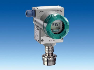

DS III with PMC connection
|
|
Mã sản phẩm:
7MF4133/7MF4134/7MF4135
Tên sản phẩm:
DS III with PMC connection
ITRANS P, DS III series for gage pressure with PMC connection for the paper industry |
|---|
| | HART | PROFIBUS PA or Foundation fieldbus | Input | | Measured variable | Gage pressure | Spans (infinitely adjustable) or nominal measuring range and max. permissible test pressure | Span | Max. perm. test pressure | Nominal measuring range | Max. perm. test pressure | | | 0.01 ... 1 bar g
(0.15 ... 14.5 psi g) | 6 bar g
(87 psi g) | 1 bar g
(14.5 psi g) | 6 bar g
(87 psi g) | | | 0.04 ... 4 bar g
(0.58 ... 58 psi g) | 10 bar g
(145 psi g) | 4 bar g
(58 psi g) | 10 bar g
(145 psi g) | | | 0.16 ... 16 bar g
(2.32 ... 232 psi g) | 32 bar g
(464 psi g) | 16 bar g
(232 psi g) | 32 bar g
(464 psi g) | Lower measuring limit | | | Measuring cell with silicone oil filling | 100 mbar a (1.45 psi a) | Upper measuring limit | 100 % of max. span | Output | | | Output signal | 4 ... 20 mA | Digital PROFIBUS PA or Foundation fieldbus signal | Lower limit (infinitely adjustable) | 3.55 mA, factory preset to 3.84 mA | - | Upper limit (infinitely adjustable) | 23 mA, factory preset to 20.5 mA or optionally set to 22.0 mA | - | Load | | Without HART communication | RB ≤ (UH - 10.5 V)/0.023 A in Ω,
UH : Power supply in V | - | With HART communication | RB = 230 ... 500 Ω (SIMATIC PDM) or
RB = 230 ... 1100 Ω (HART Communicator) | - | Physical bus | - | IEC 61158-2 | With polarity reversal protection | - | Yes | Accuracy | Acc. to EN 60770-1 | Reference conditions
(All error data refer always refer to the set span) | Increasing characteristic, start-of-scale value 0 bar, stainless steel seal diaphragm, silicone oil filling, room temperature 25 °C (77 °F)) r: Span ratio
(r = max. span / set span) | Error in measurement and fixed-point setting (including hysteresis and repeatability) | | Linear characteristic | | ≤ 0.075 % | r ≤ 10 | ≤ (0.0029 · r + 0.071)% | | 10 < r ≤ 30 | ≤ (0.0045 · r + 0.071)% | | 30 < r ≤ 100 | ≤ (0.005 · r + 0.05)% | | Long-term drift (temperature change ±30 °C (±54 °F)) | ≤ (0.25 · r)% every 5 years | ≤ 0.25 % every 5 years | Influence of ambient temperature | | at -10 ... +60 °C (14 ... 140 °F) | ≤ (0.08 · r + 0.1)% | ≤ 0.3 % | at -40 ... -10 °C and +60 ... +85 °C
(-40 ... +14 °F and 140 ... 185 °F) | ≤ (0.1·r + 0.15) %/10 K | ≤ 0.25 %/10 K | Influence of the medium temperature (only with flush-mounted diaphragm) | | Temperature difference between medium temperature and ambient temperature | 3 mbar/10 K (0.04 psi/10 K) | Influence of mounting position | ≤ 0.1 mbar g (0.00145 psi g) per 10° inclination | Measured Value Resolution | - | 3 · 10-5 of nominal measuring range | Rated operating conditions | | Degree of protection (to EN 60529) | IP65, IP68, NEMA 4X, enclosure cleaning, resistant to lyes, steam to 150° C (302 °F) | Temperature of medium | -20 ... +100 °C (-4 ... +212 °F) | Ambient conditions | | Ambient temperature | -20 ... +85 °C (-4 ... +185 °F) | Storage temperature | -50 ... +85 °C (-58 ... +185 °F) | Climatic class | | Condensation | Permissible | Electromagnetic Compatibility | | Emitted interference | Acc. to EN 50081-1 | Interference immunity | Acc. to EN 61326 and NAMUR NE 21 | Design | | Weight (without options) | ≈ 1.5 kg (≈ 3.3 lb) | Enclosure material | Low-copper die-cast aluminum GD-AlSi 12 | Wetted parts materials | | Gasket (standard) | PTFE flat gasket | O-ring (minibolt) | FPM (Viton) or optionally: FFPM or NBR | Measuring cell filling | Silicone oil or inert filling liquid | Process connection (standard) | Flush-mounted, 1½", PMC Standard design | Process connection (minibolt) | Flush-mounted, 1", minibolt design | Power supply UH | | Supplied through bus | Terminal voltage on transmitter | 10.5 ... 45 V DC
10.5 ... 30 V DC in intrinsically-safe mode | - | Separate 24 V power supply necessary | - | No | Bus voltage | | Not Ex | - | 9 ...32 V | With intrinsically-safe operation | - | 9 ...24 V | Current consumption | | Basic current (max.) | - | 12.5 mA | Startup current ≤ basic current | - | Yes | Max. current in event of fault | - | 15.5 mA | Fault disconnection electronics (FDE) available | - | Yes | Certificates and approvals | | | Classification according to PED 97/23/EC | For gases of fluid group 1 and liquids of fluid group 1; complies with requirements of article 3, paragraph 3 (sound engineering practice) |
HART communication | |
|---|
HART communication | 230 ... 1100 Ω | Protocol | HART Version 5.x | Software for computer | SIMATIC PDM |
PROFIBUS PA communication | |
|---|
Simultaneous communication with master class 2 (max.) | 4 | The address can be set using | Configuration tool or local operation (standard setting address 126) | Cyclic data usage | | | 5 (one measured value) or
10 (two measured values) | | 0, 1, or 2 (register operating mode and reset function for metering) | Internal preprocessing | | Device profile | PROFIBUS PA Profile for Process Control Devices Version 3.0, Class B | Function blocks | 2 | | | - Adaptation to customer-specific process variables
| Yes, linearly rising or falling characteristic | - Electrical damping T63 , adjustable
| 0 to 100 s | | Input /Output | | parameterizable (last good value, substitute value, incorrect value) | | Yes, one upper and lower warning limit and one alarm limit respectively | | Can be reset, preset, optional direction of counting, simulation function of register output | | parameterizable (summation with last good value, continuous summation, summation with incorrect value) | | One upper and lower warning limit and one alarm limit respectively | | 1 | Transducer blocks | 2 | - Pressure transducer block
| | - Can be calibrated by applying two pressures
| Yes | - Monitoring of sensor limits
| Yes | - Specification of a container characteristic with
| Max. 30 nodes | - Square-rooted characteristic for flow measurement
| Yes | - Gradual volume suppression and implementation point of square-root extraction
| Parameterizable | - Simulation function for measured pressure value and sensor temperature
| Constant value or over parameterizable ramp function |
Communication Foundation fieldbus | |
|---|
Function blocks | 3 function blocks analog input, 1 function block PID | | | - Adaptation to customer-specific process variables
| Yes, linearly rising or falling characteristic | - Electrical damping T63 , adjustable
| 0 to 100 s | | Output/input (can be locked within the device with a bridge) | | parameterizable (last good value, substitute value, incorrect value) | | Yes, one upper and lower warning limit and one alarm limit respectively | - Square-rooted characteristic for flow measurement
| Yes | | Standard FF function block | | 1 resource block | Transducer blocks | 1 transducer block Pressure with calibration, 1 transducer block LCD | - Pressure transducer block
| | - Can be calibrated by applying two pressures
| Yes | - Monitoring of sensor limits
| Yes | - Simulation function: Measured pressure value, sensor temperature and electronics temperature
| Constant value or over parameterizable ramp function |
|
|
|
|
|
|

SITRANS P300 (gage pressure and absolute pressure)
|
|
Mã sản phẩm:
7MF8023/7MF8024/7MF8025
Tên sản phẩm:
SITRANS P300 (gage pressure and absolute pressure)
SITRANS P300 for gage and absolute pressure |
|---|
| | HART | PROFIBUS PA and FOUNDATION fieldbus | Gage pressure input | | | Measured variable | Gage pressure (flush-mounted) | Spans (infinitely adjustable) or nominal measuring range and
max. permissible test pressure | Measuring span | Max. perm. test pressure | Nominal measuring range | Max. perm. test pressure | | | 0.01 ... 1 bar g
(0.15 ... 14.5 psi g) | 6 bar g
(87 psi g) | 1 bar g
(14.5 psi g) | 6 bar g
(87 psi g) | | | 0.04 ... 4 bar g
(0.58 ... 58 psi g) | 10 bar g
(145 psi g) | 4 bar g
(58 psi g) | 10 bar g
(145 psi g) | | | 0.16 ... 16 bar g
(2.3 ... 232 psi g) | 32 bar g
(464 psi g) | 16 bar g
(232 psi g) | 32 bar g
(464 psi g) | | | 0.6 ... 63 bar g
(9.1 ... 914 psi g) | 100 bar g
(1450 psi g) | 63 bar g
(914 psi g) | 100 bar g
(1450 psi g) | | | 1.6 ... 160 bar g
(23.2 ... 2321 psi g) | 250 bar g
(3626 psi g) | 160 bar g
(2321 psi g) | 250 bar g
(3626 psi g) | | | 4.0 ... 400 bar g
(58 ... 5802 psi g) | 500 bar g
(7252 psi g) | 400 bar g
(5802 psi g) | 500 bar g
(7252 psi g) | | | Depending on the process connection, the span may differ from these values | | Lower measuring limit | | - Measuring cell with silicone oil
| 30 mbar a (0.44 psi a) | Upper measuring limit | | - Measuring cell with silicone oil
| 100 % of max. span | 100 % of the max. nominal measuring range | Absolute pressure input | | Measured variable | Absolute pressure | Spans (infinitely adjustable) or nominal measuring range and
max. permissible test pressure | Measuring span | Max. perm. test pressure | Nominal measuring range | Max. perm. test pressure | | | 8 ... 250 mbar a
(0.12 ... 3.6 psi a) | 2 bar a
(29 psi a) | 250 mbar a
(3.6 psi a) | 2 bar a
(29 psi a) | | | 0.043 ... 1.30 bar a
(0.62 ... 19 psi a) | 10 bar a
(145 psi a) | 1.30 bar a
(19 psi a) | 10 bar a
(145 psi a) | | | 0.16 ... 5 bar a
(2.3 ... 73 psi a) | 30 bar a
(435 psi a) | 5 bar a
(73 psi a) | 30 bar a
(435 psi a) | | | 1 ... 30 bar a
(14.5 ... 435 psi a) | 100 bar a
(1450 psi a) | 30 bar a
(435 psi a) | 100 bar a
(1450 psi a) | Lower measuring limit | | - Measuring cell with silicone oil
| 0 mbar a (0 psi a) | Upper measuring limit | | - Measuring cell with silicone oil
| 100% of max. span | 100 % of the max. nominal measuring range | Input of gage pressure, with flush-mounted diaphragm | | | Measured variable | Gage pressure (flush-mounted) | Spans (infinitely adjustable) or nominal measuring range and max. permissible test pressure | Measuring span | Max. perm. test pressure | Nominal measuring range | Max. perm. test pressure | | | 0.01 ... 1 bar g (0.15 ... 14.5 psi g) | 6 bar g
(87 psi g) | 1 bar g
(14.5 psi g) | 6 bar g
(87 psi g) | | | 0.04 ... 4 bar g (0.58 ... 58 psi g) | 10 bar g
(145 psi g) | 4 bar g
(58 psi g) | 10 bar g
(145 psi g) | | | 0.16 ... 16 bar g (2.32 ... 232 psi g) | 32 bar g
(464 psi g) | 16 bar g
(232 psi g) | 32 bar g
(464 psi g) | | | 0.6 ... 63 bar g (9.14 ... 914 psi g) | 100 bar g
(1450 psi g) | 63 bar g
(914 psi g) | 100 bar g
(1450 psi g) | Lower measuring limit | 100 mbar a (0 psi a) | Upper measuring limit | | - Measuring cell with silicone oil
| 100 % of max. span | 100 % of the max. nominal measuring range | Input of absolute pressure, with flush-mounted diaphragm | | | Measured variable | Absolute pressure (flush-mounted) | Spans (infinitely adjustable) or nominal measuring range and
max. permissible test pressure | Measuring span | Max. perm. test pressure | Nominal measuring range | Max. perm. test pressure | | | 43 ... 1300 mbar a
(0.62 ... 18.9 psi g) | 10 bar a
(145 psi a) | 1300 mbar a
(18.9 psi a) | 10 bar a
(145 psi a) | | | 0.16 ... 5 bar a
(2.32 ... 72.5 psi a) | 30 bar a
(435 psi a) | 5 bar a
(72.5 psi a) | 30 bar a
(435 psi a) | | | 1 ... 30 bar a
(14.5 ... 435 psi a) | 100 bar a
(1450 psi a) | 30 bar a
(435 psi a) | 100 bar a
(1450 psi a) | | | Depending on the process connection, the span may differ from these values | | Lower measuring limit | 0 bar a (0 psi a) | Upper measuring limit | | - Measuring cell with silicone oil
| 100% of max. span | 100 % of the max. nominal measuring range | Output | | Output signal | 4 ... 20 mA | Digital PROFIBUS PA signal | Physical bus | - | IEC 61158-2 | With polarity reversal protection | No | Yes | Electrical damping T63 (step width 0.1 s) | Set to 0.1 s (0 ... 100 s) | Measuring accuracy | | Reference conditions
(All error data refer always refer to the set span) | Increasing characteristic, start-of-scale value 0 bar, stainless steel seal diaphragm, measuring cell with silicone oil, room temperature 25 °C (77 °F), span ratio (r = max. span / set span) | Measurement deviation with limit setting, including hysteresis and repeatability. | | | | Gage pressure | Absolute pressure | Absolute pressure, flush-mounted | Gage pressure | Absolute pressure | Absolute pressure, flush-mounted | Linear characteristic | | | | ≤ 0.075 % | ≤ 0.01 % | ≤ 0.02 % | | ≤ (0.0029 · r + 0.071)% | ≤ 0.1 % | ≤ 0.2 % | | | | ≤ (0.0045 · r + 0.071)% | ≤ 0.2 % | ≤ 0.4 % | | | | ≤ (0.005 · r + 0.05)% | - | - | | | Settling time T63without electrical damping | Approx. 0.2 s | Long-term drift at ±30 °C (±54 °F) | ≤ (0.25 · r)%/5 years | ≤ (0.1 · r)%/year | ≤ 0.25 %/5 years | ≤ 0.1 %/year | Influence of ambient temperature | | - at -10 ... +60 °C (14 ... 140 °F)
| ≤ (0.1 · r + 0.2)% | ≤ (0.2 · r + 0.3)% | ≤ 0.3 % | ≤ 0.5 % | - at -40 ... -10 °C and +60 ... +85 °C
(-40 ... 14 °F and 140 ... 185 °F)
| ≤ (0.1·r + 0.15) %/10 K | ≤ (0.2·r + 0.3) %/10 K | ≤ 0.25 %/10 K | ≤ 0,5 %/10 K | Influence of the medium temperature (only with flush-mounted diaphragm) | | - Temperature difference between medium temperature and ambient temperature
| 3 mbar/10 K (0.04 psi/10 K) | Conditions of use | | Installation conditions | | Ambient temperature | Observe the temperature class in areas subject to explosion hazard. | - Measuring cell with silicone oil
| -40 ... +85 °C (-40 ... +185 °F) | - Measuring cell with Neobee oil (with flush-mounted diaphragm)
| -10 ... +85 °C (14 ... +185 °F) | - Measuring cell with inert liquid (not with flush-mounted diaphragm)
| -20 ... +85 °C (-4 ... +185 °F) | | -30 ... +85 °C (-22 ... +185 °F) | | -50 ... +85 °C (-58 ... +185 °F)
(for Neobee: -20 ... +85 °C (-4 ... +185 °F)) | Climatic class | | Condensation | Permissible | Degree of protection acc. to EN 60529 | IP65, IP68, NEMA X, enclosure cleaning, resistant to lyes, steam to 150° C (302 °F) | Electromagnetic Compatibility | | - Emitted interference and interference immunity
| Acc. to EN 61326 and NAMUR NE 21 | Medium conditions | | Temperature of medium | | - Measuring cell with silicone oil
| -40 ... +100 °C (-40 ... +212 °F) | - Measuring cell with silicone oil (with flush-mounted diaphragm)
| -40 ... +150 °C (-40 ... +302 °F) | - Measuring cell with Neobee oil (with flush-mounted diaphragm)
| -10 ... +150 °C (-14 ... +302 °F) | - Measuring cell with silicone oil, with temperature decoupler (only with flush-mounted diaphragm)
| -40 ... +200 °C (-40 ... +392 °F) | - Measuring cell with inert liquid
| -20 ... +100 °C (-4 ... +212 °F) | - Measuring cell with high-temperature oil
| -10 ... +250 °C (14 ... 482 °F) | Design (standard version) | | Weight (without options) | Approx. 800 g (1.8 lb) | Enclosure material | Stainless steel, mat. No. 1.4301/304 | Material of parts in contact with the medium | | | Stainless steel, mat. No. 1.4404/316L or Hastelloy C276, mat. No. 2.4819 | | Stainless steel, mat. No. 1.4404/316L | | Stainless steel, mat. No. 1.4404/316L or Hastelloy C276, mat. No. 2.4819 | | - Silicone oil
- Inert filling liquid
| Process connection | - G½B to EN 837-1
- Female thread ½-14 NPT
- Oval flange PN 160 (MWP 2320 psi) with fastening thread:
- 7â„16-20 UNF to IEC 61518
| Design (version with flush-mounted diaphragm) | | Weight (without options) | Approx. 1 … 13 kg (2.2 … 29 lb) | Enclosure material | Stainless steel, mat. No. 1.4301/304 | Material of parts in contact with the medium | | | Stainless steel, mat. No. 1.4404/316L | | Stainless steel, mat. No. 1.4404/316L | | - Silicone oil
- Inert filling liquid
- FDA compliant fill fluid (Neobee oil)
| Process connection | - Flanges as per EN and ASME
- F&B and pharmaceutical flanges
| Power supply UH | | Terminal voltage on transmitter | 10.5 ... 42 V DC
for intrinsically safe operation: 10.5 ... 30 V DC | Supplied through bus | Separate power supply | - | Not necessary | Bus voltage | | | | - | 9 ... 32 V | - With intrinsically-safe operation
| - | 9 ... 24 V | Current consumption | | | | - | 12.5 mA | - Startup current ≤ basic current
| - | Yes | - Max. fault current in the event of a fault
| - | 15.5 mA | Fault disconnection electronics (FDE) | - | Available | Certificates and approvals | | Classification according to PED 97/23/EC | For gases of fluid group 1 and liquids of fluid group 1; complies with requirements of Article 3, paragraph 3 (sound engineering practice) | Water, waste water | In preparation | Explosion protection | | Intrinsic safety "i" | PTB 05 ATEX 2048 | Marking | Ex II 1/2 G EEx ia/ib IIB/IIC T4, T5, T6 | Permissible ambient temperature | | | -40 ... +85 °C (-40 ... +185 °F) | | -40 ... +70 °C (-40 ... +158 °F) | | -40 ... +60 °C (-40 ... +140 °F) | Interface | To certified intrinsically-safe circuits with maximum values: Ui = 30 V, Ii = 100 mA,
Pi = 750 mW, Ri = 300 Ω | To certified intrinsically-safe circuits with maximum values: FISCO supply unit: Ui = 17.5 V, Ii = 380 mA,
Pi = 5.32 W Linear barrier: Ui = 24 V, Ii = 250 mA, Pi = 1.2 W | Effective inner capacitance: | Ci = 6 nF | Ci = 1.1 nF | Effective internal inductance: | Li = 0.4 mH | Li ≤ 7 μH | Explosion protection to FM for USA andUS)Canada (cFM | | | - Identification (DIP) or (IS); (NI)
| Certificate of Compliance 3025099 CL I, DIV 1, GP ABCD T4 ... T6; CL II, DIV 1, GP EFG; CL III; CL I, ZN 0/1 AEx ia IIC T4 ... T6; CL I, DIV 2, GP ABCD T4 ... T6; CL II, DIV 2, GP FG; CL III | - Identification (DIP) or (IS)
| Certificate of Compliance 3025099C CL I, DIV 1, GP ABCD T4 ... T6; CL II, DIV 1, GP EFG; CL III; Ex ia IIC 4 ... T6; CL I, DIV 2, GP ABCD T4 ... T6; CL II, DIV 2, GP FG; CL III |
HART communication | |
|---|
HART communication | 230 ... 1100 Ω | Protocol | HART Version 5.x | Software for computer | SIMATIC PDM |
PROFIBUS PA communication | |
|---|
Simultaneous communication with master class 2 (max.) | 4 | The address can be set using | Configuration tool Local operation (standard setting Address 126) | Cyclic data usage | | | One measured value: 5 bytes Two measured values: 10 bytes | | Register operating mode: 1 bytes Reset function due to metering. 1 bytes | Device profile | PROFIBUS PA Profile for Process Control Devices Version 3.0, Class B | Function blocks | 2 | | | - Adaptation to customer-specific process variables
| Linearly rising or falling characteristic | | 0 ... 100 s adjustable | | Input /Output | | One upper and lower warning limit and one alarm limit respectively | | Can be reset and preset Optional direction of counting Simulation function of the register output | | One upper and lower warning limit and one alarm limit respectively | | 1 | Transducer blocks | 2 | - Pressure transducer block
| | - Monitoring of sensor limits
| Yes | - Specification of a container characteristic with
| Max. 31 nodes | | Linear | | Available | - Transducer block "Electronic temperature"
| | | Available |
Communication Foundation Fieldbus | |
|---|
Function blocks | 3 function blocks analog input, 1 function block PID | | | - Adaptation to customer-specific process variables
| Yes, linearly rising or falling characteristic | - Electrical damping T63 , adjustable
| 0 to 100 s | | Output/input (can be locked within the device with a bridge) | | parameterizable (last good value, substitute value, incorrect value) | | Yes, one upper and lower warning limit and one alarm limit respectively | - Square-rooted characteristic for flow measurement
| Yes | | Standard FF function block | | 1 resource block | Transducer blocks | 1 transducer block Pressure with calibration, 1 transducer block LCD | - Pressure transducer block
| | - Can be calibrated by applying two pressures
| Yes | - Monitoring of sensor limits
| Yes | - Simulation function: Measured pressure value, sensor temperature and electronics temperature
| Constant value or over parameterizable ramp function |
|
|
|
|
|
|
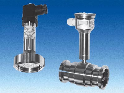

SITRANS P Compact, for pressure and absolute pressure
|
|
Mã sản phẩm:
7MF8010
Tên sản phẩm:
SITRANS P Compact, for pressure and absolute pressure
Pressure transmitters for food, pharmaceuticals and biotechnology | Mode of operation | | Measuring principle | Piezo-resistive | Input | | Measured variable | Gage or absolute pressure | Measuring range | 0 ... 160 mbar (0 ... 2.32 psi)
...
0 ... 40 bar (0 ... 580 psi) | Output | | Output signal | | | 4 ... 20 mA | | 0 ... 20 mA | Measuring accuracy | to EN 60770-1 | Linearity error including hysteresis (reference point adjustment) | = 0.2 % of full-scale value | Adjustment accuracy | = ± 0.2 % of full-scale value | Response time | < 20 ms | Influence of ambient temperature | | On the enclosure | | | < 0.2 %/10 K of full-scale value | | < 0.2 %/10 K of full-scale value | On the process connection (remote seals) | Zero error (depends on design) | | | | 4.8 mbar/10 K (0.070 psi/10 K) | | 2.3 mbar/10 K (0.033 psi/10 K) | | 1.6 mbar/10 K (0.023 psi/10 K) | | 0.6 mbar/10 K (0.009 psi/10 K) | | | | 9.5 mbar/10 K (0.138 psi/10 K) | | 4.1 mbar/10 K (0.060 psi/10 K) | | 3.9 mbar/10 K (0.057 psi/10 K) | | 3.9 mbar/10 K (0.057 psi/10 K) | The zero error specified for the process connection should be considered as a guideline for a standard design. We will produce a detailed system calculation on request. Systems with reduced remote seal errors are available on request. | Rated conditions | | Installation conditions | | | Any, vertical as standard | Ambient conditions | | | -10 ... +70 °C (14 ... 158 °F) | | -10 ... +90 °C (14 ... 194 °F) | | Max. 200 °C (392 °F), depending on design | - Degree of protection (to EN 60529)
| IP65, optional IP67 | - Electromagnetic compatibility
| | | To EN 50081 Part 1, issue 1993 (residential and industrial areas). The unit has no own emissions. | | EN 50082 Part 2, issue March 1995 (industrial areas) | Construction | | Weight (without remote seal) | | | ˜ 460 g (˜ 1.01 lb) | | ˜ 200 g (˜ 0.44 lb) | Enclosure | | | - Field housing IP65 or IP67, with screwed gland
- Angled plug DIN 43650, IP65
- Cable connection, IP67
- Round plug connector M12, IP65
| | Stainless steel, mat. No. 1.4404/316L/1.4305 | Material of union nut | Polyamide (with electrical connection using plug or cable) Electronics unit potted with silicone Internal ventilation for measuring ranges < 16 bar (< 232 psi), through housing thread or connecting cable depending on design | Process connection | | | See ordering data | | Stainless steel, mat. No. 1.4404/316L | Power supply | | Terminal voltage on transmitter | 10 ... 30 V DC | Rated voltage | 24 V DC | Certificates and approvals | | Classification according to pressure equipment directive (DRGL 97/23/EC) | For gases of fluid group 1 and liquids of fluid group 1; complies with the requirements of Article 3, paragraph 1 (appendix 1); assigned to category III, conformity evaluation module H by the TÜV Nord | Explosion protection | | | TÜV 03 ATEX 2099 X | | Ex II 2G EEx ib IIC T6 |
|
|
|
|
|
|
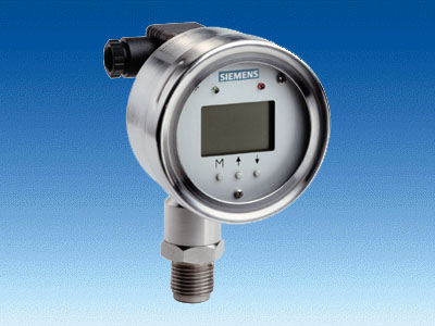

ZD series (gage pressure, absolute pressure and level)
|
|
Mã sản phẩm:
7MF1580
Tên sản phẩm:
ZD series (gage pressure, absolute pressure and level)
SITRANS P pressure transmitters, ZD series | | Mode of operation | | Measuring principle | Thin-film strain gauge | Input | | Measured variable | Gage and absolute pressure | Measured range | Resolution | 0 ... 2 bar (0 ... 29 psi) | 0.6 mbar (0.008 psi) | 0 ... 10 bar (0 ... 145 psi) | 3 mbar (0.044 psi) | 0 ... 50 bar (0 ... 725 psi) | 15 mbar (0.218 psi) | 0 ... 200 bar (0 ... 2900 psi) | 60 mbar (0.9 psi) | 0 ... 400 bar (0 ... 5802 psi) | 120 mbar (1.8 psi) | Measured range | Overload limit | 0 ... 2 bar (0 ... 29 psi) | 5 bar (72.5 psi) | 0 ... 10 bar (0 ... 145 psi) | 25 bar (363 psi) | 0 ... 50 bar (0 ... 725 psi) | 120 bar (1740 psi) | 0 ... 200 bar (0 ... 2900 psi) | 500 bar (7250 psi) | 0 ... 400 bar (0 ... 5802 psi) | 600 bar (8700 psi) | Range adjustment (turndown) | 5:1 (max. 10:1) | Output | | Output signal | 4 ... 20 mA | Lower current limit | min. 3.6 mA | Upper current limit | max. 23 mA | Output protected against | Reversed polarity, overvoltage and short-circuiting | Max. load | R B = (UH - 12 V) / 0.023 A | Voltage measurement | Linear rising | Measuring accuracy | To EN 60770-1 | Error in measurement (including non-linearity, hysteresis and repeatability, at 25 °C (77 °F)) | < 0.25 % of full-scale value (typical), max. 0.5 % | Adjustment time | < 100 ms | Long-term drift | 0.25 % of full scale value/year | Influence of ambient temperature | | | < ±0.25 %/10 K of full-scale value | | ±0.5 %/10 K of full-scale value | Vibration influence | 0.05 %/g to 500 Hz in all directions (to IEC 68‑2‑64) | Power supply effect | < ±0.01 %/V of full-scale value | Rated conditions | | Ambient conditions | | | -25 ... +85 °C (-13 ... +185 °F) | - Temperature for best readability
| -10 ... +70 °C (14 ... 158 °F) | | -40 ... +85 °C (-40 ... +185 °F) | Medium conditions | | | -30 ... +100 °C (-22 ... +212 °F) | Degree of protection | IP65 to EN 60529 | Electromagnetic compatibility | | - Emitted interference and noise immunity
| To EN 61 326/A1 appendix A (1998) | Displays and controls | | Display | LCD, max. 5 digits, digit height 9 mm | Decimal point | Freely parameterizable | Limit values | Freely parameterizable | Limit violation display | Red LED and message on LCD
(↑symbol /↓symbol in case of limit violation in upward / downward direction) | Parameterization | With 3 keys | Units | mA or % or physical variable (default setting: bar) Other dimensions: mbar, kPa, MPa, mmH20, mH20, psi, inH20, mmHg, kg/cm², torr, atm | Damping | Between 0.1 and 100 s (increment: 0.1 s) freely parameterizable | Design | | Weight | ≈0.6 kg (≈1.32 lb) | Electrical connection | Using 2-pole plug connector with M16x1.5‑Cable inlet to EN 175301‑803A, plastic | Process connection | - Male thread G½B and female thread G1/8B
- G½B to EN 837-1
- Female thread: ½-14 NPT
| Version of housing/process connection | - Radial (type A), can be swiveled by max. ±120° (α)
| | | - Axial (type B), can be swiveled by max. ±360°
| Material | | Non-wetted parts materials | | | ∅ 80 mm (3.15 inch), stainless steel mat. No. 1.4016 | | Stainless steel, mat. No. 1.4016 with glass | Wetted parts materials | | | Al2O3 | | Viton | | Stainless steel, mat. No. 1.4571/316Ti | Power supply | | Terminal voltage on pressure transmitter (UH) | 12 ... 30 V DC | Certificate and approvals | | Classification according to pressure equipment directive 97/23/EC | For gases of fluid group 1 and liquids of fluid 1; complies with requirements of article 3, paragraph 3 (sound engineering practice) |
|
|
|
|
|
|
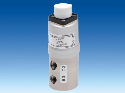

SITRANS P250 (differential pressure)
|
|
Mã sản phẩm:
7MF1641
Tên sản phẩm:
SITRANS P250 (differential pressure)
SITRANS P250 differential pressure transmitter |
|---|
Application | Differential pressure transmitter | Liquids and neutral gases | Mode of operation | Measuring principle | Piezo-resistive measuring cell (ceramic diaphragm) | Input | Measured variable | Differential pressure | Measuring range | 0 ... 0.1 to 0 ... 25 bar (0 ... 1.45 to 0 ... 363 psi) | Operating pressure | ≤ 25 bar (363 psi) at a differential pressure range < 6 bar (87 psi) ≤ 50 bar (725 psi) at a differential pressure range > 10 bar (145 psi | Burst pressure | 1.5 x operating pressure | Output | | Output signal | | | 4 ... 20 mA | | 0 ... 5 V and 0 ... 10 V DC | Load | | 3-wire | > 10 kΩ | 2-wire | ≤ (UH - 11 V) / 0.02 A | Measuring accuracy | | Dynamic behavior (at 25°C (77°F), including conformity error, hysteresis and repeatability) | ≤ 1 % of typical full-scale value, see "Measuring range" table | Long-term drift acc. to IEC 60770 | ≤ 0.5 % of full-scale value/year | Influence of ambient temperature | | | ≤ 0.6 %/10K of full-scale value (≤ 1.2 % / 10K for measuring cell 0 ... 0.1 bar (1.45 psi)) | | ≤ 0.22 %/10K of full-scale value (≤ 0.37 % / 10K for measuring cell 0 ... 0.1 bar (1.45 psi)) | Dynamic behavior | Suitable for static and dynamic measurements | Response time T99 | < 5 ms | Load variation | < 50 Hz |
Conditions of use | |
|---|
Ambient conditions | | | -15 ...+ 85 °C (5 ... 185 °F) | | -15 ...+ 85 °C (5 ... 185 °F) | | -40 ...+ 85 °C (-40 ... +185 °F) | Degree of protection acc. to EN 60529 | IP65 | Mounting position | Any | Mounting | Mounting bracket, included in delivery | Design | | Weight | Approx. 430 g (approx. 0.95 lb) | Enclosure material | Stainless steel 1.4305/AISI 303 | Electrical connection | - Plug EN 175301-803-A
- Circular plug EN 60130-9
- Cable 1.5 m
| Process connection | - Hose sleeve Ø 4 mm/6 mm
- Pipe union Ø 6 mm/8 mm
- Male thread 7/16-20 UNF, G1/8
- Female thread 1/8-27 NPT
- (Standard), G1/8
| Wetted parts materials | | | Stainless steel 1.4305/AISI 303, CuZn nickel-plated | | Ceramic Al2O3 (96 %) | | FPM (standard), EPDM, NBR, MVQ, CR | Power supply UH | | Terminal voltage on pressure transmitter | | | 11 ... 33 V DC | | 11 ... 33 V DC/ 24 V AC ±15 % | | 18 ... 33 V DC/ 24 V AC ±15 % | Current consumption at nominal pressure | | | < 20 mA | | < 5 mA | Protection against polarity reversal | Protected against short-circuit and polarity reversal. Each connection against the other with max. supply voltage. | Certificates and approvals | | Approval | CE conformity |
Measuring range | | Max. permissible operating pressure
(on either side) | Burst pressure | Max. permissible operating pressure
(on one side) | Accuracy |
|---|
[bar] | [psi] | | | | | 0 ... 0.1 | 0 ... 1.45 | 25 bar
(363 psi) | 37.5 bar
(544 psi) | 0.6 bar
(8.7 psi) | ≤ 1.0 % | 0 ... 0.2 | 0 ... 2.9 | 25 bar
(363 psi) | 37.5 bar
(544 psi) | 0.6 bar
(8.7 psi) | ≤ 0.8 % | 0 ... 0.25 | 0 ... 3.63 | 25 bar
(363 psi) | 37.5 bar
(544 psi) | 0.6 bar
(8.7 psi) | ≤ 0.5 % | 0 ... 0.3 | 0 ... 4.35 | 25 bar
(363 psi) | 37.5 bar
(544 psi) | 0.6 bar
(8.7 psi) | ≤ 0.5 % | 0 ... 0.4 | 0 ... 5.8 | 25 bar
(363 psi) | 37.5 bar
(544 psi) | 1.2 bar
(17.4 psi) | ≤ 0.8 % | 0 ... 0.5 | 0 ... 7.25 | 25 bar
(363 psi) | 37.5 bar
(544 psi) | 1.2 bar
(17.4 psi) | ≤ 0.5 % | 0 ... 0.6 | 0 ... 8.7 | 25 bar
(363 psi) | 37.5 bar
(544 psi) | 1.2 bar
(17.4 psi) | ≤ 0.5 % | 0 ... 1 | 0 ... 14.5 | 25 bar
(363 psi) | 37.5 bar
(544 psi) | 2 bar
(29psi) | ≤ 0.5 % | 0 ... 1.6 | 0 ... 23.2 | 25 bar
(363 psi) | 37.5 bar
(544 psi) | 3.2 bar
(46.4 psi) | ≤ 0.5 % | 0 ... 2.5 | 0 ... 36.3 | 25 bar
(363 psi) | 37.5 bar
(544 psi) | 5 bar
(72.5 psi) | ≤ 0.5 % | 0 ... 4 | 0 ... 58 | 25 bar
(363 psi) | 37.5 bar
(544 psi) | 8 bar
(116 psi) | ≤ 0.5 % | 0 ... 6 | 0 ... 87 | 25 bar
(363 psi) | 37.5 bar
(544 psi) | 12 bar
(174 psi) | ≤ 0.5 % | 0 ... 10 | 0 ... 145 | 50 bar
(725 psi) | 75 bar
(1088 psi) | 20 bar
(290 psi) | ≤ 0.5 % | 0 ... 16 | 0 ... 232 | 50 bar
(725 psi) | 75 bar
(1088 psi) | 32 bar
(464 psi) | ≤ 0.5 % | 0 ... 25 | 0 ... 363 | 50 bar
(725 psi) | 75 bar
(1088 psi) | 50 bar
(725 psi) | ≤ 0.5 % |
|
|
|
|
|
|
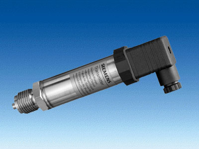

Z series for gage pressure
|
|
Mã sản phẩm:
7MF1562/7MF1564
Tên sản phẩm:
Z series for gage pressure
SITRANS P pressure transmitter, Z series for gage pressure |
|---|
Mode of operation | | Measuring principle | Thin-film strain gauge | Input | | Measured variable | Gage pressure | Measured range | 0 to 16 bar g (0 to 232 psi g) or 0 to 25 bar g (0 to 363 psi g) | Output | | Current output signal | 4 ... 20 mA | Measuring accuracy | To EN 60770-1 | Error in measurement (at 25 °C (77 °F), including conformity error, hysteresis and repeatability) | 0.5 % of full-scale value - typical | Response time T99 | < 0.1 s | Long-term drift | | | 0.3 % of full-scale value/year - typical | | 0.3 % of full-scale value/year - typical | Influence of ambient temperature | | | 0.3 %/10 K (0.3 %/10 K) of full-scale value - typical | | 0.3 %/10 K (0.3 %/10 K) of full-scale value - typical | Rated conditions | | Medium conditions | | | -30 ... +120 °C (-22 ... +248 °F) | Degree of protection to EN 60529 | IP65 | Ambient conditions | | | -25 ... 85 °C (-13 ... +185 °F) | | -50 ... 100 °C (-58 ... +212 °F) | Design | | Weight | ≈ 0.2 kg (≈ 0.44 lb) | Wetted parts materials | | | Al2O3 - 96 % | | Brass, mat. No. 2.0402 | | Viton | Process connection | Male thread G½B
female thread G1/8B | Power supply | | Terminal voltage on pressure transmitter | | | 10 to 36 V DC | Certificate and approvals | | Classification according to pressure equipment directive (DRGL 97/23/EC) | For gases of fluid group 1 and liquids of fluid 1; complies with requirements of article 3, paragraph 3 (sound engineering practice) |
|
|
|
|
|
|
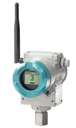

SITRANS P280
|
|
Mã sản phẩm:
7MP1120
Tên sản phẩm:
SITRANS P280
Description The SITRANS P280 is a WirelessHART pressure transmitter that provides all measured process values as well as diagnostic information, parameters and functions via radio. The device is powered by an internal battery and designed for ultralow power consumption. The compact and rugged design makes it specially suitable for direct mounting on tanks and pipes in remote parts of plants, and on moving or rotating equipment for process monitoring or asset management applications. Various pressure ranges available (2,10, 50, 200, 400 bar) LCD display with functional display items and icons, English and German display selectable Practical push buttons: Three push buttons for maximum efficiency for setup, diagnostics, communication and security settings with no additional devices or tools Maintenance-friendly backlight function Sleep mode for efficient battery life management Battery status display on LCD and in network overview Precise measurement accuracy for more productivity 90 and 180 degree display turnable Configurable with standard tools supporting EDD – e. g. with SIMATIC PDM Physical HART maintenance port for commissioning
|
|
Overview:
Features:
Video clips:
Screen shots:
Links:
|
|